|
There are basically two different styles of aftermarket cold air intake (CAI) systems available for the BMW M3: one has a short intake pipe with a cone filter attached and a heat shield to reduce intake temperatures (i.e. - Conforti, ECIS, AA, and PAR), and the other type has a longer intake pipe that positions the cone filter down inside the front bumper to completely separate it from the heat of the engine bay (i.e. - Dinan and Benfer).
Both intake systems can cost anywhere from $200 to $400 depending on the brand, quality, and materials used, but the Dinan/Benfer style is considered to be more of a true cold air intake.
A custom cold air intake based on the Dinan/Benfer design was constructed for under $75 with simple parts that you can order online, and hardware that you can pick up at your local auto parts or hardware store.
Click on image to view a detailed parts list |
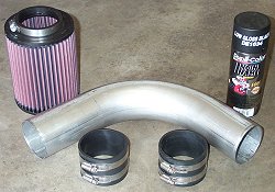
Parts Needed
The cold air intake system consists of one K&N cylindrical air filter (5" diameter, 6.5" long), one 90ş mandrel bent 3" aluminized steel exhaust tubing elbow, two 3" intake pipe rubber hose couplers, one can of high temperature ceramic based engine spray paint, and one strip of 1/8"x3/4" flat aluminum.
Click on image to view a detailed
parts source and price list
|
|
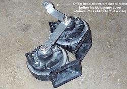
Horns Relocated
In order to fit the filter down inside the bumper, the horns must be relocated.
Using the flat strip of 1/8"x3/4" aluminum, a new bracket is fabricated that will relocate both horns farther inside the bumber and completely out of the way.
The front bumper cover must be removed for adequate access to the area where the horns will be relocated. |
Click on image to view additional detailed photos
|

Click on image to view a larger version |
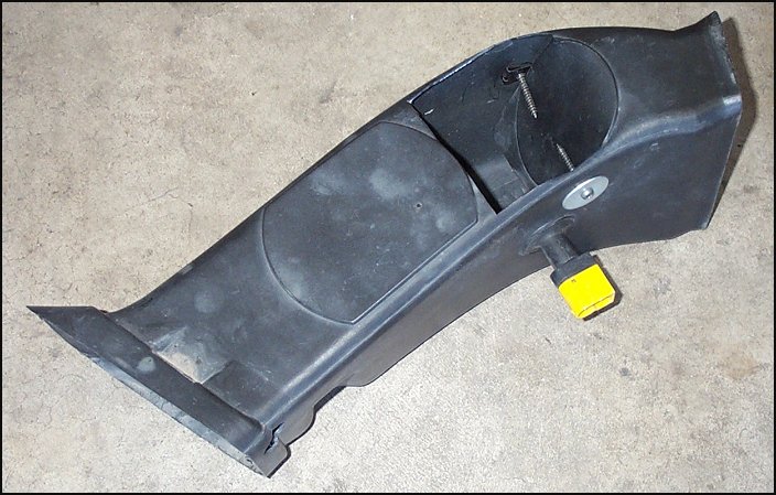
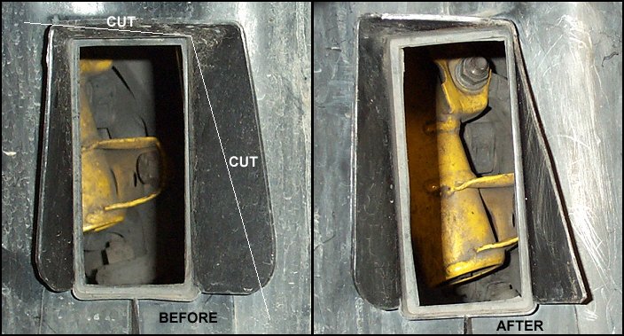
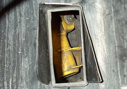
Modified Brake Duct
To provide cool air to the air filter, the driver's side brake duct is modified by cutting a flap in the top and folding it down inside the duct at an angle where it is held in position with two screws.
This angled flap directs cooler outside air coming in through the brake duct directly onto the air filter that will be positioned directly above the duct.
The flap does not completely block the duct, so it still functions as a brake cooling duct.
|
|
Wheelwell Liner Trimmed
The upper corner of the area on the inner driver's side wheelwell liner, where the back of the brake duct connects, must be trimmed slightly to make room for the air filter.
The soft plastic can easily be cut with sissors or a utility knife. |
Click on image to view a larger version
|
Click on image to view a larger version |
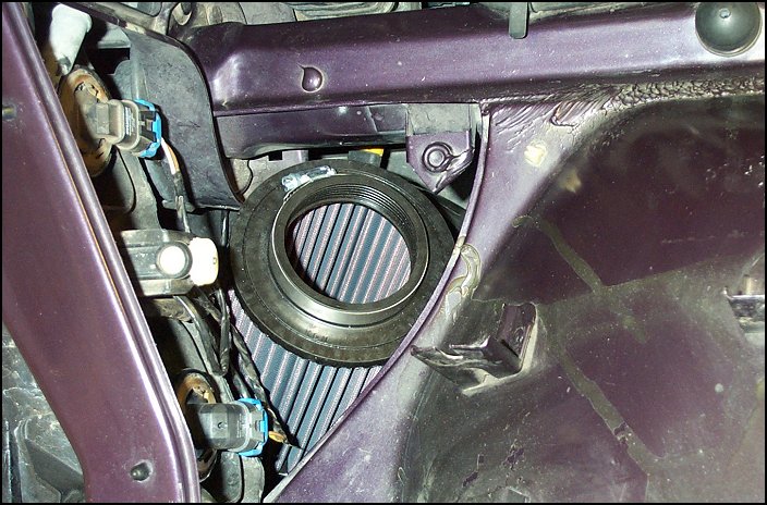
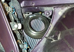
Air Filter Positioning
With the horns relocated, the wheelwell liner trimmed, and the bumper and modified brake duct reinstalled, there is now room to slide the air filter down inside the bumper at a slight angle directly above the modified brake duct where it will be provided with a constant flow of cool air.
There is enough room to remove and service the filter from inside the engine compartment, so that the bumper does not have to be removed each time (unless you have euro-spec ellipsoid headlights).
|
|
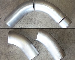
Cutting Intake Piping
The 90ş mandrel bent 3" aluminized steel elbow must be cut into two pieces, and one of the two pieces may have to be trimmed for length depending on the final air filter positioning.
The measurement and angle of the cuts were not specific as there is room for adjustment with the hose couplers during assembly of the pipes. |
Click on image to view additional detailed photos
|
Click on image to view additional detailed photos |
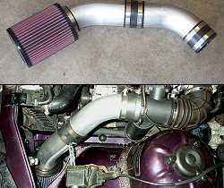
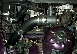
Assembled System
The two pipes are then assembled together and attached to the HFM using the two hose couplers.
The two intake pipe pieces should then be positioned to create a smooth flowing path from the air filter positioned in the bumper directly to the HFM.
The assembled pipes are also supported by a bracket that is mounted to one of the original airbox mounting points.
|
|
High Temp Paint
Once the angles, lengths, and final positioning of the intake pipes have been determined, the system can then be disassembled and the intake pipes thoroughly cleaned, prepped, and painted (inside and out) with a ceramic based high temperature paint.
Once the high temp paint on the intake piping has completely dried, the whole system can be reassmbled for a finished product. |
Click on image to view additional detailed photos
|
"What do I do with the OEM airbox sensor on my OBD1 (pre-'96) car?"
|